Before I proceed with my new post here on Learn Electrical Engineering for Beginners, I would like to thank those who sent their email for some questions. Keep those emails coming in. If you don't received an email from me that means the answer is already here on my blog or I will answer you on my future post. Please read below portion of this site for your guidance.
I hope you are now learning with this site. We are now moving on with our topic and let's study the next part of Electric Circuits which is DC Parallel Circuits.
One objective of this lesson is for you to understand that you can solve any circuits because all circuits are made of combinations of series and /or parallel circuits.
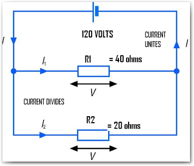
Previously, in DC Series Circuits we defined that whether resistors, lamps or cells are connected end-to-end. Today, the scenario would be completely different. Instead of being connected end-to end as in series circuit, they are connected side by side therefore it would create more than one path in which the current can flow. If this is so, we can say that resistors/resistances are said to be parallel connected or connected in parallel. The circuit would now be called a parallel circuit. The image below is one example of the parallel circuit. I show you this illustration because the diagram already explains everything.
 As what I mentioned in our earlier topic about electric circuits, we cannot say a complete circuit if we do not have a source of emf connected to them. For instance, we have two resistors connected their wire in parallel or parallel connected. When any two terminals are connected across the voltage source just as what had shown above, the whole arrangement- both resistors, the wires connecting them together and the voltage source - forms complete parallel circuit.
The circuit above shows that there are more than one path of current to flow. This means that these two resistors shares on the total current drawn from the battery. A part of the total current goes through the first resistor and at the same time a part of the total current also drawn for the second resistor. If you will intend to connect a device with polarity, for example a cell or batteries, you must connect the positive terminals together and the negative terminals together.
The Voltage in Parallel Circuit
When the resistances are connected in parallel just like the diagram above and connected across the voltage source, the voltage across each resistors are always the same. Observe the diagram that the labels used were just the same. It was self-explained in the diagram that the voltage are just the same.
Since, it is the fact that voltages across each resistances are just always the same. It has a practical consequence. What do I mean with this? This means that all components which are to be connected in parallel must have the same voltage rating if they are to work properly. Did you noticed that?
The line voltage throughout the Philippines is 220 volts. In U.S. 120 volts. I think you are aware that some of our appliances are rated 120 volts or 220 volts work properly well. If in case you have a lamp or a bulb rated 20 volts. What the hell do you think will happen? The bulb will be burn immediately because the excess current will flow through it.
Since, all appliances are connected across the same voltage source, the same voltage will also experienced across each load. Each load must be properly rated to handle this voltage.
How the Current Flow in Parallel Circuits
In order to understand well the flow of current in the circuit for parallel connections. I made a little details on the diagram above. Take a look on the diagram below:
 As I mentioned earlier, the flow of current in the parallel connections divides through each of the parallel paths. In the circuit diagram above, the two branches named them AB and CD connected in parallel. Observe that as the current flowing in each branches will divide and reunite them at node B returning to voltage source. You will wonder how the amount of current divides in each branches.
The amount of current that will serve in each branches will depend on the resistance value. This will be the principle: The current flowing through the several branches of a parallel circuit divides in inverse proportions, governed by the comparative resistance of the individual branches.
And so? what does this mean?
It only means that the lower resistance value in any branch circuit in proportion to the resistance of other branches in the same parallel circuit, the higher will be the current value or proportion which that branch will take.
Simply...
In parallel circuit, branches having low resistance draw more current than other branches having high resistance.
Like voltage, the flow of current connected in parallel circuit is also of a great importance. For instance, like we know that every electrical appliances connected in parallel, the current will divide unequally to each branch since they have differing value of resistances- the highest current flowing through the lowest resistance. You will learn more about this when we reached the protection against excessive flow of current.
Ohhh... I love to illustrate example again through problem solving. Let's take a sample problem for you to show that it really happens. Let's take again the circuit above and assign values for them.
Given that, I = 9 amperes ; I1 = 3 amperes ; I2 = 6 amperes
 For instance, a total current I = 9 amperes is flowing through the parallel branch of R1 and R2. If you will observe, the value of R1 is twice the value of R2. We have mentioned earlier that the current divides in inverse proportion to the values of the two resistors. Therefore, only 3 amperes will flow on R1 and 6 amperes will flow on R2. If for example, R1 triple its resistance from 40 ohms to 120 ohms. The current flowing through R1 will be reduced from 3 amperes to 3/3 ampere or 1 ampere while I2 would remain unchanged. Thus the total current would be 6 amperes + 1 ampere = 7 amperes.
What does it implies?
Since, in series circuit we said that all currents are the same throughout the circuit. In parallel circuit we just add it. This can be expressed mathematically as, It = I1 + I2 + I3 +...
What if the resistances are equal in parallel circuit? This will be the next topic.
Equal Resistors in Parallel Circuits
Let's consider a water pipes connected in parallel as shown in the diagram below.
 Let's say we have a constant water pressure incoming or the head as we learned in fluid dynamics. Assuming the same cross-sectional area of water pipes connected in parallel. The amount of water here would flow is equivalent to cross sectional area of pipe 1 + pipe 2.What do you think would happened to the amount of water flowing in the system if you would convert it to single pipe only? The amount of water will be less than that connected in parallel. Why? because you reduced cross sectional area in which the water would flow. The bigger the cross sectional area, the more water would flow on the system shown above.
The same thing in resistor. The bigger the cross sectional of resistor, the more current would flow because the resistor value diminishes as the cross sectional area is getting bigger.
The conclusion here is that : resistors or loads connected in parallel present a lower combined resistance or load than does any one of them individually.
This means that if you have four 400 ohms resistors connected in parallel. The resistance of the combined load will be equally divided into 4 equal resistances thereby giving you a 100 ohms total resistance. In other words, 100 ohms is your combined resistances of four 400 ohms connected in parallel.
If you don't get my point here, let's discuss it when we illustrate more problem solving in DC Parallel Circuits.
To be continued.....
Cheers!
I hope you are now learning with this site. We are now moving on with our topic and let's study the next part of Electric Circuits which is DC Parallel Circuits.
One objective of this lesson is for you to understand that you can solve any circuits because all circuits are made of combinations of series and /or parallel circuits.
Previously, in DC Series Circuits we defined that whether resistors, lamps or cells are connected end-to-end. Today, the scenario would be completely different. Instead of being connected end-to end as in series circuit, they are connected side by side therefore it would create more than one path in which the current can flow. If this is so, we can say that resistors/resistances are said to be parallel connected or connected in parallel. The circuit would now be called a parallel circuit. The image below is one example of the parallel circuit. I show you this illustration because the diagram already explains everything.
 As what I mentioned in our earlier topic about electric circuits, we cannot say a complete circuit if we do not have a source of emf connected to them. For instance, we have two resistors connected their wire in parallel or parallel connected. When any two terminals are connected across the voltage source just as what had shown above, the whole arrangement- both resistors, the wires connecting them together and the voltage source - forms complete parallel circuit.
The circuit above shows that there are more than one path of current to flow. This means that these two resistors shares on the total current drawn from the battery. A part of the total current goes through the first resistor and at the same time a part of the total current also drawn for the second resistor. If you will intend to connect a device with polarity, for example a cell or batteries, you must connect the positive terminals together and the negative terminals together.
The Voltage in Parallel Circuit
When the resistances are connected in parallel just like the diagram above and connected across the voltage source, the voltage across each resistors are always the same. Observe the diagram that the labels used were just the same. It was self-explained in the diagram that the voltage are just the same.
Since, it is the fact that voltages across each resistances are just always the same. It has a practical consequence. What do I mean with this? This means that all components which are to be connected in parallel must have the same voltage rating if they are to work properly. Did you noticed that?
The line voltage throughout the Philippines is 220 volts. In U.S. 120 volts. I think you are aware that some of our appliances are rated 120 volts or 220 volts work properly well. If in case you have a lamp or a bulb rated 20 volts. What the hell do you think will happen? The bulb will be burn immediately because the excess current will flow through it.
Since, all appliances are connected across the same voltage source, the same voltage will also experienced across each load. Each load must be properly rated to handle this voltage.
How the Current Flow in Parallel Circuits
In order to understand well the flow of current in the circuit for parallel connections. I made a little details on the diagram above. Take a look on the diagram below:
 As I mentioned earlier, the flow of current in the parallel connections divides through each of the parallel paths. In the circuit diagram above, the two branches named them AB and CD connected in parallel. Observe that as the current flowing in each branches will divide and reunite them at node B returning to voltage source. You will wonder how the amount of current divides in each branches.
The amount of current that will serve in each branches will depend on the resistance value. This will be the principle: The current flowing through the several branches of a parallel circuit divides in inverse proportions, governed by the comparative resistance of the individual branches.
And so? what does this mean?
It only means that the lower resistance value in any branch circuit in proportion to the resistance of other branches in the same parallel circuit, the higher will be the current value or proportion which that branch will take.
Simply...
In parallel circuit, branches having low resistance draw more current than other branches having high resistance.
Like voltage, the flow of current connected in parallel circuit is also of a great importance. For instance, like we know that every electrical appliances connected in parallel, the current will divide unequally to each branch since they have differing value of resistances- the highest current flowing through the lowest resistance. You will learn more about this when we reached the protection against excessive flow of current.
Ohhh... I love to illustrate example again through problem solving. Let's take a sample problem for you to show that it really happens. Let's take again the circuit above and assign values for them.
Given that, I = 9 amperes ; I1 = 3 amperes ; I2 = 6 amperes
 For instance, a total current I = 9 amperes is flowing through the parallel branch of R1 and R2. If you will observe, the value of R1 is twice the value of R2. We have mentioned earlier that the current divides in inverse proportion to the values of the two resistors. Therefore, only 3 amperes will flow on R1 and 6 amperes will flow on R2. If for example, R1 triple its resistance from 40 ohms to 120 ohms. The current flowing through R1 will be reduced from 3 amperes to 3/3 ampere or 1 ampere while I2 would remain unchanged. Thus the total current would be 6 amperes + 1 ampere = 7 amperes.
What does it implies?
Since, in series circuit we said that all currents are the same throughout the circuit. In parallel circuit we just add it. This can be expressed mathematically as, It = I1 + I2 + I3 +...
What if the resistances are equal in parallel circuit? This will be the next topic.
Equal Resistors in Parallel Circuits
Let's consider a water pipes connected in parallel as shown in the diagram below.
 Let's say we have a constant water pressure incoming or the head as we learned in fluid dynamics. Assuming the same cross-sectional area of water pipes connected in parallel. The amount of water here would flow is equivalent to cross sectional area of pipe 1 + pipe 2.What do you think would happened to the amount of water flowing in the system if you would convert it to single pipe only? The amount of water will be less than that connected in parallel. Why? because you reduced cross sectional area in which the water would flow. The bigger the cross sectional area, the more water would flow on the system shown above.
The same thing in resistor. The bigger the cross sectional of resistor, the more current would flow because the resistor value diminishes as the cross sectional area is getting bigger.
The conclusion here is that : resistors or loads connected in parallel present a lower combined resistance or load than does any one of them individually.
This means that if you have four 400 ohms resistors connected in parallel. The resistance of the combined load will be equally divided into 4 equal resistances thereby giving you a 100 ohms total resistance. In other words, 100 ohms is your combined resistances of four 400 ohms connected in parallel.
If you don't get my point here, let's discuss it when we illustrate more problem solving in DC Parallel Circuits.
To be continued.....
Cheers!


8 comments:
it is very usefull in my PLC wiring.
Thanks Mr. Endar.
If you know someone who are looking for basic concept of electrical engineering. Invite them to visit my blog.
Hi Richard,
For the meantime, you may consult Mr. Francois about HVAC. I will temporarily stop the posting here due to some reasons. You can visit his blog here at: http://engineering.electrical-equipment.org/
Hi Author
I follow your blog for a long time and must tell you that your posts always prove to be of a high value and quality for readers. Keep it up.
i really love learning about circuits it is super fun. I am only in 5th grade but still, i think science is super cool.
sir,
thank you so much for this blog because this big chance for me to know some basic electrical engineering..i am so very honor of blog..
thank you.
thank you for give this type of information.i hope it will be help for all electrical and electronic engineering and also for beginner.
i,m on my way to become elec engineering i really love it keep it up .
Post a Comment